TBOS Software Architecture: How the Magic Happens (Part 2 of 2)
Part 1 of this series discussed the four key components of the Tanktwo Battery Operating System (TBOS): T-Block, TBOS Control Unit, TCP/IP Network, and user devices. We also delved into the nuts and bolts of T-Blocks and the TBOS Control Unit.
This post illustrates how these different pieces work together to deliver TBOS’s innovative capabilities.
TBOS Software in Action
These use cases show how the components in the TBOS software architecture work together.
System Wakeup
An external signal triggers the wake-up sequence in the TMUs and starts the software components.
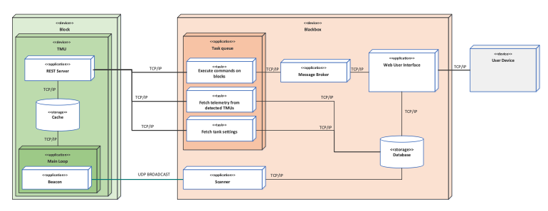
Step 1: Hierarchy and Redundancy
After the TMU loads the OS and starts the main loop process, the TMU redundancy software kicks in to ensure that only one of the two TMUs in a T-Block takes control of the unit. It runs a handshake sequence to confirm that the two TMUs it connects with are in the same T-Block and that the TCP/IP network extends to all T-Blocks in the system.
If the TMU redundancy software finds another TMU, the algorithm selects the optimal TMU and allows it to take control. If it doesn’t detect a second TMU, the first one will assume control. This process prevents two TMUs from controlling the unit simultaneously.
Step 2: Cell Discovery
After gaining control of the T-Block, the TMU runs a discovery process. Block and cell EEPROMs detect the type of hardware, and cell sensors provide information on all available cells in the system. Then, the TMU cache stores the resulting list of cells, including their state and location in the system.

Step 3: T-Block Discovery
The control unit runs the scanner application, which listens to UDP broadcast packets containing the TMU state and IP address. After discovering an active TMU, scheduled tasks use the endpoint at the TMU REST server to read the TMU state, settings, and telemetry. Then, they store the values in the control unit’s database.
The web user interface fetches information from the database and visualizes the state of the active T-Blocks via the control unit UI — allowing the operator to set desired voltage levels for the selected T-Blocks and control the system’s state using the user device(s).
System Charging and Discharging
An operator selects an operation mode in the user device’s graphic interface, and the external command activates the system. (Alternatively, a machine-to-machine interface using a REST API may send commands to the control unit.)
The message broker in the control unit receives the commands and relays them to the appropriate task in the task queue. Then, the command execution task issues the commands to the selected T-Blocks via their TMU REST server endpoints.
When managing system-level commands, the control unit runs an internal logic to determine the system topology and match the desired voltage levels. Let’s say, a system consists of 4 T-Blocks, 2 in series and 2 in parallel (2S2P). When a user sets the system output voltage at 200V, the web user interface assesses the system topology, dividing the desired output voltage by the number of T-Blocks in series. The control unit then gives the message broker a command to issue 100V output voltage for all T-Blocks in the system.
The TMU gathers data from the cells using the cell sensors and stores this data in the cache during charging and discharging. The control unit queries the information, iterates through all the detected T-Blocks, and stores the latest telemetry values in its database to automate processes such as cell balancing, determining SoH, yellow-flagging, and more.
The web user interface then processes this data and visualizes it via the user device — allowing the operator to make informed decisions and adjust the system’s behaviors on the fly.
TL;DR: How TBOS Software Works
We put software on top of a generic block of battery cells, which receives commands from the control unit, and make it do very cool things that even industry veterans deem impossible.
The control unit oversees all the activities within the system — it takes commands from the user device, makes the calculations, and tells each T-Block what to do. It also provides real-time data visualization through the user device to support decision-making on a dime.
A TCP/IP network connects all these devices and gets everything to talk to everything to make any battery nerd’s dreams come true.
But, of course, there are a lot of nuances. The software makes the magic happen by allowing us to program individual battery cells to behave and work together in ways that are out of reach for traditional battery systems — providing features and capabilities that will make TBOS and SDBs the backbone of any sustainable and profitable electrification solutions.